DESCRIPTION & HISTORY
Taking up a course at Mt Druitt TAFE called “Engineering Technical (Mechanical) Diploma”, we have been given an end of the year assignment. The assignment was to design a car robot that had to guide itself out of a maze by using infrared or ultra sonic technology.
This assignment started at James Kok’s class who was one of my lecturers that taught Mechatronic’s, and also Tim Lovett another one of my lecturer who taught the 3D Modeling and Mechanical Engineering classes.
The assignment had a generic guide line on how to create the car robot. The platform was to be cut from plastic (Polycarbonate 4.5mm thick) using a CNC mill, and the design was up to each individual student to incorporate the gearbox, batteries, picaxe module, wheels and the sensor circuit. For our sensor circuit, we were given two different technologies to use. One of them was the Infrared circuit and the other was the Ultrasonic Sensor module.
After doing some research, I thought I would do something different compared to the other students who had used the Polycarbonate for their base. My thoughts had pointed me to designing my own printed circuit board (PCB) for my base and integrating the infrared circuit on there. I then thought of making previsions to also use the ultrasonic sensors as an option incase I was to use that technology. By doing this, it eliminates messy wirings that run across the sensor circuits to the picaxe module.
Printed Circuit Board (PCB)
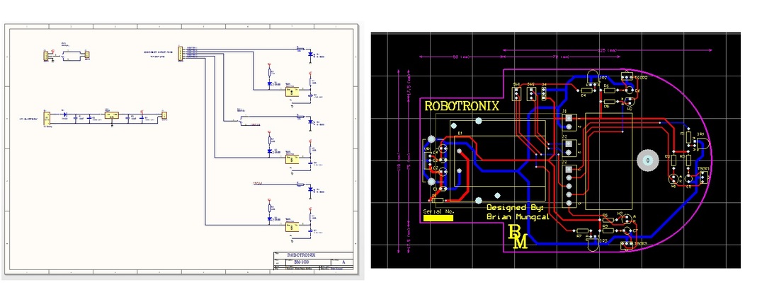
My first step to designing the PCB was to sketch up a schematic using a software called Protel DXP. I thought of using infrared for my sensing, so I sketched up three infrared circuits and noted down which input pins to use from the picaxe module. To give power to my circuit, I sketched up a 5 volts d.c regulator circuit powered by a 9 volts battery. This has given a constant 5 volts supply to my I.R / ultrasonic sensors and picaxe module. I then added three switches. The first one was to turn the supplied power on and off. The second was to switch from the right sensing program to the left sensing program. The third switch controlled which sensor to use between the right sensor and the left sensor. I then added a row of mini PCB mount connectors that gave me access to connecting from the PCB to the picaxe module by using a small wire loom.
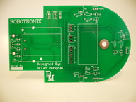
When laying out the PCB, I had to measure the gearbox, wheels, picaxe module and the battery packs. I had to make sure that I had no collisions and my mounting holes were sized and located correctly.
When laying out the PCB, I had to measure the gearbox, wheels, picaxe module and the battery packs. I had to make sure that I had no collisions and my mounting holes were sized and located correctly.
PICAXE-28X2 Development Kit
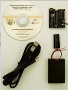
The main brain of Robotronix was the PICAXE-28X2 chip that was plugged on to a project development board. I purchased the PICAXE-28X2 Development Kit form MicroZed Computers. The kit includes a PICAXE-28X2 chip, 28-pin project board, switched battery box, software CD, and USB programming cable. The programming I wrote for Robotronix was all written in a basic program called Q-Basic.
SRF005 – Ultrasonic Sensor
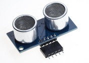
At the beginning I have intended to use the infrared circuit for this assignment. But after some extensive amount of testing, I was unhappy with the distance I was getting from the sensors to the wall. To eliminate this issue, I decided to us the SRF005 Ultra Sonic Sensors.
I am now able to achieve the right distance I need to run Robotronix through the maze without touching the walls. The SRF005 Ultrasonic sensors actually give me the flexibility to change my distance when ever I need to by simply changing the calculation on my program to run my sensors.
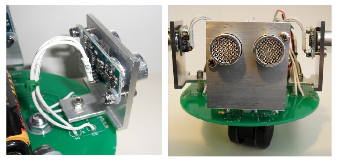
In choosing the SRF005, I have had to modify and include mounting hole on my PCB to mount the custom made brackets that held up the SRF005 sensors.
The SRF005 Ultrasonic sensor has 5 pins, but only uses 4 pins to connect to. It was also very easy for me to connect these pins to the PCB by choosing the right pads to solder the wires to.
I am now able to achieve the right distance I need to run Robotronix through the maze without touching the walls. The SRF005 Ultrasonic sensors actually give me the flexibility to change my distance when ever I need to by simply changing the calculation on my program to run my sensors.
In choosing the SRF005, I have had to modify and include mounting hole on my PCB to mount the custom made brackets that held up the SRF005 sensors.
The SRF005 Ultrasonic sensor has 5 pins, but only uses 4 pins to connect to. It was also very easy for me to connect these pins to the PCB by choosing the right pads to solder the wires to.
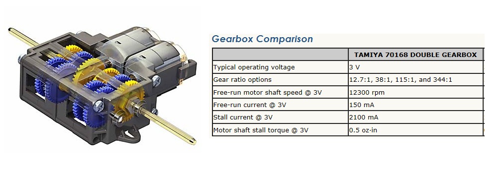
TAMIYA GEARBOX
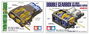
Originally I bought the Tamyia 70097 Twin Gearbox that had two different types of optional gear ratio. They were 58:1 & 203:1. I had set the gear ratio to 203:1 which towards the end was running to fast. I then dropped the gear ratio down to 58:1 and found it was running to slow. To solve my issue I ended up buying the Tamiya 70168 Double Gearbox which gave me four different types of optional gear ratio, and these were 12.7:1, 38:1, 115:1, and 344:1. I had set the gear ratio to 115:1 and found it was running perfectly to the speed I wanted Robotronix to run to.